Wednesday 27 May 2015

3D printing technology and its applications


The 3D printing technology made its way to the technological world in the year 1986, but not gain importance until 1990. It was not that popular outside the world of engineering, architecture and manufacturing. 3D printing is also known as desktop fabrication, it can form any material that can be obtained as a powder. For creating an object you need a digital 3D-model. You can scan a set of 3D images, or draw it using computer-assisted design or CAD software. You can also download them from internet. The digital 3D-model is usually saved in STL format and then sent to the printer. The process of "printing" a three-dimensional object layer-by-layer with equipment, which is quite similar with ink-jet printers. One of the most important applications of 3D printing is in the medical industry. With 3D printing, surgeons can produce mockups of parts of their patient's body which needs to be operated upon.3D printing make it possible to make a part from scratch in just hours. It allows designers and developers to go from flat screen to exact part. Nowadays almost everything from aerospace components to toys are getting built with the help of 3D printers. 3D printing can provide great savings on assembly costs because it can print already assembled products. With 3D printing, companies can now experiment with new ideas and numerous design iterations with no extensive time or tooling expense. They can decide if product concepts are worth to allocate additional resources. 3D printing could even challenge mass production method in the future. 3D printing is going to impact so many industries, such as automotive, medical, business & industrial equipment, education, architecture, and consumer-product industries. 3D printing or additive manufacturing is a process of making three dimensional solid objects from a digital file. The creation of a 3D printed object is achieved using additive processes. In an additive process an object is created by laying down successive layers of material until the entire object is created. Each of these layers can be seen as a thinly sliced horizontal cross-section of the eventual object. It all starts with making a virtual design of the object you want to create. This virtual design is made in a CAD (Computer Aided Design) file using a3D modeling program (for the creation of a totally new object) or with the use of a 3D scanner (to copy an existing object). A 3D scanner makes a 3D digital copy of an object. 3d scanners use different technologies to generate a 3d model such as time-of-flight, structured / modulated light, volumetric scanning and many more. Recently, many IT companies like Microsoft and Google enabled their hardware to perform 3d scanning, a great example is Microsoft’s Kinect. This is a clear sign that future hand-held devices like smartphones will have integrated 3d scanners. Digitizing real objects into 3d models will become as easy as taking a picture. Prices of 3d scanners range from very expensive professional industrial devices to 30 USD DIY devices anyone can make at home. 3D printer is unlike of the common printers. On a 3D printer the object is printed by three dimension. A 3D model is built up layer by layer. Therefore the whole process is called rapid prototyping, or 3D printing. The resolution of the current printers are among the 328 x 328 x 606 DPI (xyz) at 656 x 656 x 800 DPI (xyz) in ultra-HD resolution. The accuracy is 0.025 mm - 0.05 mm per inch. The model size is up to 737 mm x 1257 mm x 1504 mm. The biggest drawback for the individual home user is still the high cost of 3D printer. Another drawback is that it takes hours or even days to print a 3D model (depending on the complexity and resolution of the model). Besides above, the professional 3D software and 3D model design is also in a high cost range. Alternatively there are already simplified 3D printers for hobbyist which are much cheaper. And the materials it uses is also less expensive. These 3D printers for home use are not as accurate as commercial 3D printer. Not all 3D printers use the same technology. There are several ways to print and all those available are additive, differing mainly in the way layers are build to create the final object. Some methods use melting or softening material to produce the layers. Selective laser sintering (SLS) and fused deposition modeling (FDM) are the most common technologies using this way of printing. Another method of printing is when we talk about curing a photo-reactive resin with a UV laser or another similar power source one layer at a time. The most common technology using this method is called stereolithography (SLA). To be more precise: since 2010, the American Society for Testing and Materials (ASTM) group “ASTM F42 – Additive Manufacturing”, developed a set of standards that classify the Additive Manufacturing processes into 7 categories according to Standard Terminology for Additive Manufacturing Technologies. These seven processes are: Vat Photopolymerisation Material Jetting Binder Jetting Material Extrusion Powder Bed Fusion Sheet Lamination Directed Energy Deposition One of the most important applications of 3D printing is in the medical industry. With 3D printing, surgeons can produce mockups of parts of their patient's body which needs to be operated upon. 3D printing make it possible to make a part from scratch in just hours. It allows designers and developers to go from flat screen to exact part. Nowadays almost everything from aerospace components to toys are getting built with the help of 3D printers. 3D printing is also used for jewelry and art, architecture, fashion design, art, architecture and interior design.

Monday 25 May 2015

How to file a patent, IPR in India


Intellectual property rights are the rights given to persons over the creations of their minds. They usually give the creator an exclusive right over the use of his/her creation for a certain period of time. The importance of intellectual property in India is well established at all levels- statutory, administrative and judicial. India ratified the agreement establishing the World Trade Organisation (WTO). This Agreement, inter-alia, contains an Agreement on Trade Related Aspects of Intellectual Property Rights (TRIPS) which came into force from 1st January 1995. It lays down minimum standards for protection and enforcement of intellectual property rights in member countries which are required to promote effective and adequate protection of intellectual property rights with a view to reducing distortions and impediments to international trade. The obligations under the TRIPS Agreement relate to provision of minimum standard of protection within the member countries legal systems and practices. The Agreement provides for norms and standards in respect of following areas of intellectual property Patents Trade Marks Copyrights Geographical Indications Industrial Designs Patents The basic obligation in the area of patents is that, invention in all branches of technology whether products or processes shall be patentable if they meet the three tests of being new involving an inventive step and being capable of industrial application. In addition to the general security exemption which applied to the entire TRIPS Agreement, specific exclusions are permissible from the scope of patentability of inventions, the prevention of whose commercial exploitation is necessary to protect public order or morality, human, animal, plant life or health or to avoid serious prejudice to the environment. Further, members may also exclude from patentability of diagnostic, therapeutic and surgical methods of the treatment of human and animals and plants and animal other than micro-organisms and essentially biological processes for the production of plants and animals.

Saturday 23 May 2015

Project report writing Plagiarism and academic honesty


1 Introduction A technical report is a formal report designed to convey technical information in a clear and easily accessible format. It is divided into sections which allow different readers to access different levels of information. This guide explains the commonly accepted format for a technical report; explains the purposes of the individual sections; and gives hints on how to go about drafting and refining a report in order to produce an accurate, professional document. 11 Originality and plagiarism Whenever you make use of other people's facts or ideas, you must indicate this in the text with a number which refers to an item in the list of references. Any phrases, sentences or paragraphs which are copied unaltered must be enclosed in quotation marks and referenced by a number. Material which is not reproduced unaltered should not be in quotation marks but must still be referenced. It is not sufficient to list the sources of information at the end of the report; you must indicate the sources of information individually within the report using the reference numbering system. Information that is not referenced is assumed to be either common knowledge or your own work or ideas; if it is not, then it is assumed to be plagiarised i.e. you have knowingly copied someone else's words, facts or ideas without reference, passing them off as your own. This is a serious offence. If the person copied from is a fellow student, then this offence is known as collusion and is equally serious. Examination boards can, and do, impose penalties for these offences ranging from loss of marks to disqualification from the award of a degree This warning applies equally to information obtained from the Internet. It is very easy for markers to identify words and images that have been copied directly from web sites. If you do this without acknowledging the source of your information and putting the words in quotation marks then your report will be sent to the Investigating Officer and you may be called before a disciplinary panel. • Plagiarism refers to the unacknowledged borrowing of others’ writing. When you use others’ exact words without citing their work, you are guilty of plagiarizing, whether you “borrow” an entire report or a single sentence. In academic contexts, plagiarism is a form of academic dishonesty. In university classrooms, the teacher usually assumes that the work you turn in is your own original work. If you turn in work that is not your own or that was co-created with others, you are obliged to make that clear to your instructor. When you borrow language from other sources, you are expected to use quotation marks and provide a full bibliographical reference. Whenever you borrow graphics or quote passages, you are legally and ethically obliged to acknowledge that use, following appropriate conventions for document sources. If you have doubts about whether or not you are using your own or others’ writing ethically and legally, ask your instructor. • Plagiarism is misrepresenting someone else’s work as your own, taking someone else’s writing or ideas and passing them off as your own work. Plagiarism refers to stealing ideas as well as words, while copyright refers only to exact expression. Some acts of plagiarism are also copyright violations, but some are not. Some acts of plagiarism are covered by law (e.g., copyright violations), but other acts of plagiarism are a matter of institutional or professional or general ethics. • In academic contexts, plagiarism is regarded as an issue of academic honesty. Academic honesty refers to the ethics, codes, and guidelines under which the academic community does its learning, its teaching, its academic work. Those guidelines are important to the university’s being able to achieve its educational mission—its goals for teaching, learning, research, and service. How to avoid plagiarism Plagiarism can sometimes be the result of poor note taking, or paraphrasing without properly citing the reference. You can avoid plagiarism by: • citing your references • referencing correctly • recording direct quotes and paraphrases correctly when note taking. Quotes When you use the exact words, ideas or images of another person, you are quoting the author. If you do not use quotation marks around the original author's direct words and cite the reference, you are plagiarising. Paraphrasing Paraphrasing is when you take someone else's concepts and put them into your own words without changing the original meaning. Even though you are not using the same words you still need to state where the concepts came from. Note taking Poor note taking can lead to plagiarism. You should always take care to: • record all reference information correctly • use quotation marks exactly as in the original • paraphrase correctly • clearly distinguish your own ideas from the ideas of other authors and researchers. 
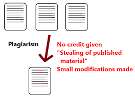
Plagiarism is when you take (i) somebody else’s idea, or (ii) somebody else’s words, and use them such that you appear to be the original creator or author of the idea or words. Even if you change a few words of someone else's sentence, it is still plagiarism if the same idea is presented. Plagiarism is a form of academic misconduct that is prohibited by the Student Code of Conduct. Plagiarism is unacceptable in all academic work and all documents authored by you, including assignments and project reports. Since published documents are stored and accessed in public places, it is quite possible that a published paper, thesis or dissertation can be accused of plagiarism, perhaps years after it is published. When you write a thesis/dissertation that includes discussion of research results from other documents, plagiarism may creep in unintentionally. Therefore, it is particularly important that you recognize plagiarism and make special efforts to avoid it. Plagiarism can also have legal consequences. Because of the Berne copyright convention, virtually all published material (including on-line, internet material) should be considered to have copyright protection whether it has a copyright notice or not. Suggestions to help you avoid plagiarism: • Take notes when you read. Do not copy complete sentences unless you want to quote the sentence. • Wait some time (or a day) after you read the original source text to write your draft. • Don't draft your paper with the original source text (or a photocopy) open next to you. Use your notes. Go back to the source later to check something you are unsure of. You can certainly use other peoples' ideas and words in your writing, as long as you give them appropriate credit. There are established methods of giving credit to your source of ideas and words. This is discussed in the following section. January 12, 2006 Examples: • If you use exact words from another source, put quotation marks around them. Example: According to Derrisen (2004), "since the flow of liquids in open channels is not subject to any pressure other than the weight of the liquid and atmospheric pressure on the surface, the theoretical analysis can be much simpler." • It is not sufficient to use the citation alone if a direct quote is used. Incorrect example: Since the flow of liquids in open channels is not subject to any pressure other than the weight of the liquid and atmospheric pressure on the surface, the theoretical analysis can be much simpler (Derrisen, 2004). • Changing a few words is not sufficient, since copying the ‘writing style’ is also plagiarism. Either use your own words or quote it. Incorrect example: Liquid flow in open channels is subject to pressure from the weight of the liquid and atmospheric pressure; therefore, the theoretical analysis is much easier (Derrisen, 2004). • Quotes are not necessary if you just use the idea. However, a citation is still required. Warning: it is almost impossible to put a single sentence into your own words. This is why you should read and understand, then write from your notes. Acceptable example: Simple models can be developed for a liquid in open channel flow since it is driven only by atmospheric pressure and weight of the liquid (Derrisen, 2004). Note that the last part of the sentence is a fact (not an idea); one can only change the wording of a fact, not the fact itself! When you describe an experiment, the facts (e.g., specifications of a piece of equipment) will be the same for all students, but the word and sentence arrangements will be different. • Put the citation where it will best identify which information is derived from which source. Place the citation after a key word or phrase which suggests a citation is needed. If most or all of a paragraph is from one source, put the citation at the end of the topic sentence. Repeat the citation later if necessary to make the source of information clear. Examples: - In a study of gear mechanics (Brable, 2005) showed that... - Several of these studies identified the critical control parameter… - Heat transfer in regenerators have been modeled by finite difference method (Jurgel, 2001) and by finite element method (Mitchell, 1996, Templeton, 2003)…. Please note that it is the responsibility of the student to avoid plagiarism in theses and dissertations. Your advisor and thesis committee can help with suggestions, but only if you discuss specific instances of a potential problem. If you are concerned about the quality of your writing, you can take the help of others to proofread your thesis.

Sunday 17 May 2015

Nanogrids: An ultimate solution for creative energy aware buildings


Nanogrids are small microgrids, typically serving a single building or a single load. Navigant Research has developed its own definition of a nanogrid as being 100 kW for grid-tied systems and 5 kW for remote systems not interconnected with a utility grid. Nanogrids mimic the innovation that is rising up from the bottom of the pyramid and capturing the imagination of growing numbers of technology vendors and investment capital, particularly in the smart building and smart transportation spaces, says Navigant. In other ways, nanogrids are more conventional than microgrids since they do not directly challenge utilities in the same way. Nanogrids are restricted to a single building or a single load, and therefore do not bump up against regulations prohibiting the transfer or sharing of power across a public right-of-way. From a technology point of view, perhaps the most radical idea behind nanogrids is a clear preference for direct current (DC) solutions, whether these systems are connected to the grid or operate as standalone systems, according to Navigant. building is often only as intelligent as the electrical distribution network it connects with. That's why smart buildings are often seen as an extension of the smart grid. Meters, building controls, intelligent lighting and HVAC systems, distributed energy systems and the software layered on top are indeed valuable for controlling localized energy use within a building. But in many cases, the building relies on the utility or regional electricity grid to value those services. Some analysts define these technologies as the "enterprise smart grid" because of their interaction with the electricity network. But what if there were no supporting centralized grid? How would buildings be designed then? In today's grid-centric framework, the building works for the benefit of the larger grid. But Nordman thinks there's a future where the opposite is true. And that future is the nanogrid. A nanogrid is different from a microgrid, according to the authors. Although some microgrids can be developed for single buildings, they mostly interface with the utility. Some aren't even fully islandable. A nanogrid, however, would be "indifferent to whether a utility grid is present." Rather, it would be a mostly autonomous DC-based system that would digitally connect individual devices to one other, as well as to power generation and storage within the building. Nordman and Christensen describe it this way: "A nanogrid is a single domain of power -- for voltage, capacity, reliability, administration, and price. Nanogrids include storage internally; local generation operates as a special type of nanogrid. A building-scale microgrid can be as simple as a network of nanogrids, without any central entity." The nanogrid is conceptually similar to an automobile or aircraft, which both house their own isolated grid networks powered by batteries that can support electronics, lighting and internet communications. Uninterruptible power supplies also perform a similar function in buildings during grid disturbances. Here's a simple diagram illustrating how a nanogrid -- based on the concept of "local power distribution" -- would function. Essentially, it would allow most devices to plug into power sockets and connect to the nanogrid, which could balance supply with demand from those individual loads.

The gyrator: A magic device to formulate an inductor


The gyrator is a 2-port network containing two current sources controlled by the terminal voltages and oppositely directed, as shown inside the rectangular outline in the figure. Its two parameters g1, g2 are transconductances, units A/V. In the figure, it is shown fed by a voltage source v and loaded by a capacitor C. The circuit is easy to solve, giving i1 = (g1g2/jωC)v, or Z = jω(C/g1g2) = jωL, so a capacitive reactance is converted to an inductive reactance. The circuit effectively inverts its load impedance, changing 1/jωC into jωC. No passive network can function as a gyrator, but with the help of operational amplifiers it is not difficult to build one. The figure shows a circuit that is sometimes called a generalized impedance converter (GIC). The circuit is shown with component values that cause it to simulate an inductance of 1 H. It is not difficult to analyze this circuit. The voltages at nodes a, c and d are equal if the feedback is working, and equal to the applied voltage. Now all the voltages can be found by starting at the lowest resistor and calculating the currents working upwards, remembering that the op-amp input currents are zero. Finally, the impedance the circuit presents to the source is just the applied voltage divided by the current. The expression is shown in the figure. Nothing in the circuit is connected to ground except the lowest impedance, so the ground connection is not essential.
The circuit was tested by applying a sinusoidal voltage of various frequencies, while measuring the voltage across the circuit and the current through it with the AC scales of two DMM's. The waveforms are sinusoidal, so the meters read properly. Between about 500 Hz and 7000 Hz, the circuit did simulate a 1 H inductor quite well. At lower frequencies, the reactance of the capacitor becomes large, and the op-amp outputs tend to saturate. At higher frequencies, the capacitive reactance becomes small and overloads the op-amps. In both cases the feedback becomes inaccurate, and the apparent inductance rises. The capacitor must be properly chosen for the frequency range desired. Note that the capacitor may also be in the position of Z2. I used LM833 and LM385 dual op-amps with essentially the same results for either. To observe the time-domain behavior, apply a square wave to the circuit through a 10k resistor. Use a unity-gain buffer to avoid loading the signal generator so the square wave does not droop. Observe the applied voltage as well as the voltage across the circuit with an oscilloscope. The voltage across the circuit decreased exponentially to zero with the expected time constant of L/R = 0.0001 s, a very pretty result. Unlike a normal inductor, the current that this circuit can absorb is limited. To draw the input voltage to zero, the lower op-amp output voltage must sink to 10k times the input current. Otherwise, the output will saturate and the feedback will fail. This would occur if we used a 1k resistor instead of a 10k resisor as the R in our RL circuit, trying to get a time constant of 1 ms. This limitation must be carefully watched in applying this circuit, and the component values should be carefully chosen to eliminate it. This is, indeed, a remarkable circuit that presents inductance without magnetic fields. Related to the gyrator is the Negative Impedance Converter, illustrated at the right. An easy analysis shows that it converts an impedance Z into its negative, -Z. This will convert a capacitive reactance 1/jωC into the inductive reactance j(1/ωC). This is not a real inductance, since the reactance decreases as the frequency increases instead of increasing. The inductance is a function of frequency, not a constant. If you test the circuit shown, a voltage V applied to the input will cause a current V/10kΩ to flow out of the input terminal, instead of into it, as would occur with a normal resistance. A 411 op-amp operates as desired with a resistive Z, but if you replace the resistance with an 0.01 μF capacitor, the circuit will oscillate (I measured 26.4 kHz), the op-amp output saturating in both directions alternately. When the op-amp was replaced by an LM748 with a (very large) compensation capacitor of 0.001 μF, the circuit behaved somewhat better. Using an AC voltmeter and milliammeter, the reactance varied from 16 kΩ at 1 kHz to 32 kHz at 500 Hz, showing that it does indeed decrease as the frequency increases. An investigation with the oscilloscope would verify that the reactance was inductive, with voltage leading the current. The waveform rapidly becomes a triangle wave at higher frequencies (because of the large compensation capacitance). It is clear that this circuit is not a practical one for converting a capacitance to an inductance, even if the strange frequency dependence is accepted.

Reverse Engineering: An nontraditional way of Engineering


Engineering is the profession involved in designing, manufacturing, constructing, and maintaining of products, systems, and structures. At a higher level, there are two types of engineering: forward engineering and reverse engineering. Forward engineering is the traditional process of moving from high-level abstractions and logical designs to the physical implementation of a system. In some situations, there may be a physical part without any technical details, such as drawings, bills-of-material, or without engineering data, such as thermal and electrical properties. The process of duplicating an existing component, subassembly, or product, without the aid of drawings, documentation, or computer model is known as reverse engineering. Reverse engineering can be viewed as the process of analyzing a system to: 1. Identify the system's components and their interrelationships 2. Create representations of the system in another form or a higher level of abstraction 3. Create the physical representation of that system Reverse engineering is very common in such diverse fields as software engineering, entertainment, automotive, consumer products, microchips, chemicals, electronics, and mechanical designs. For example, when a new machine comes to market, competing manufacturers may buy one machine and disassemble it to learn how it was built and how it works. A chemical company may use reverse engineering to defeat a patent on a competitor's manufacturing process. In civil engineering, bridge and building designs are copied from past successes so there will be less chance of catastrophic failure. In software engineering, good source code is often a variation of other good source code. In some situations, designers give a shape to their ideas by using clay, plaster, wood, or foam rubber, but a CAD model is needed to enable the manufacturing of the part. As products become more organic in shape, designing in CAD may be challenging or impossible. There is no guarantee that the CAD model will be acceptably close to the sculpted model. Reverse engineering provides a solution to this problem because the physical model is the source of information for the CAD model. This is also referred to as the part-to-CAD process. Another reason for reverse engineering is to compress product development times. In the intensely competitive global market, manufacturers are constantly seeking new ways to shorten lead-times to market a new product. Rapid product development (RPD) refers to recently developed technologies and techniques that assist manufacturers and designers in meeting the demands of reduced product development time. For example, injection-molding companies must drastically reduce the tool and die development times. By using reverse engineering, a three-dimensional product or model can be quickly captured in digital form, re-modeled, and exported for rapid prototyping/tooling or rapid manufacturing. Following are reasons for reverse engineering a part or product: 1. The original manufacturer of a product no longer produces a product 2. There is inadequate documentation of the original design 3. The original manufacturer no longer exists, but a customer needs the product 4. The original design documentation has been lost or never existed 5. Some bad features of a product need to be designed out. For example, excessive wear might indicate where a product should be improved 6. To strengthen the good features of a product based on long-term usage of the product 7. To analyze the good and bad features of competitors' product 8. To explore new avenues to improve product performance and features 9. To gain competitive benchmarking methods to understand competitor's products and develop better products 10. The original CAD model is not sufficient to support modifications or current manufacturing methods 11. The original supplier is unable or unwilling to provide additional parts 12. The original equipment manufacturers are either unwilling or unable to supply replacement parts, or demand inflated costs for sole-source parts 13. To update obsolete materials or antiquated manufacturing processes with more current, less-expensive technologies Reverse engineering enables the duplication of an existing part by capturing the component's physical dimensions, features, and material properties. Before attempting reverse engineering, a well-planned life-cycle analysis and cost/benefit analysis should be conducted to justify the reverse engineering projects. Reverse engineering is typically cost effective only if the items to be reverse engineered reflect a high investment or will be reproduced in large quantities. Reverse engineering of a part may be attempted even if it is not cost effective, if the part is absolutely required and is mission-critical to a system. Reverse engineering of mechanical parts involves acquiring three-dimensional position data in the point cloud using laser scanners or computed tomography (CT). Representing geometry of the part in terms of surface points is the first step in creating parametric surface patches. A good polymesh is created from the point cloud using reverse engineering software. The cleaned-up polymesh, NURBS (Non-uniform rational B-spline) curves, or NURBS surfaces are exported to CAD packages for further refinement, analysis, and generation of cutter tool paths for CAM. Finally, the CAM produces the physical part. It can be said that reverse engineering begins with the product and works through the design process in the opposite direction to arrive at a product definition statement (PDS). In doing so, it uncovers as much information as possible about the design ideas that were used to produce a particular product.

Electrical Power Quality issues and implications


Ideally, the best electrical supply would be a constant magnitude and frequency sinusoidal voltage waveform. However, because of the non-zero impedance of the supply system, of the large variety of loads that may be encountered and of other phenomena such as transients and outages, the reality is often different. The Power Quality of a system expresses to which degree a practical supply system resembles the ideal supply system.  If the Power Quality of the network is good, then any loads connected to it will run satisfactory and efficiently. Installation running costs and carbon footprint will be minimal.  If the Power Quality of the network is bad, then loads connected to it will fail or will have a reduced lifetime, and the efficiency of the electrical installation will reduce. Installation running costs and carbon footprint will be high and/or operation may not be possible at all. COST OF POOR POWER QUALITY Poor Power Quality can be described as any event related to the electrical network that ultimately results in a financial loss. Possible consequences of poor Power Quality include (Fig. 1):  Unexpected power supply failures (breakers tripping, fuses blowing).  Equipment failure or malfunctioning  Equipment overheating (transformers, motors, …) leading to their lifetime reduction.  Damage to sensitive equipment (PC‟s, production line control systems, …).  Electronic communication interferences.  Increase of system losses.  Need to oversize installations to cope with additional electrical stress with consequential increase of installation and running costs and associated higher carbon footprint.  Penalties imposed by utilities because the site pollutes the supply network too much.  Connection refusal of new sites because the site would pollute the supply network too much.  Impression of unsteadiness of visual sensation induced by a light stimulus whose luminance or spectral distribution fluctuates with time (flicker)  Health issues with and reduced efficiency of personnel,.. The following main contributors to Low Voltage poor Power Quality can be defined:  Reactive power, as it loads up the supply system unnecessary,  Harmonic pollution, as it causes extra stress on the networks and makes installations run less efficiently,  Load imbalance, especially in office building applications, as the unbalanced loads may result in excessive voltage imbalance causing stress on other loads connected to the same network, and leading to an increase of neutral current and neutral to earth voltage build-up,  Fast voltage variations leading to flicker. All this phenomena potentially lead to inefficient running of installations, system down time and reduced equipment life and consequently high installation running costs. In addition to financial loss due to „production stops‟, another factor of the cost of poor Power Quality can be identified by analyzing the extra kWh losses that exist due to the presence of harmonic pollution in typical network components such as transformers, cables and motors. As this loss has to be supplied by the utility power plants, a financial loss and CO2 emissions can be assigned to it. Exact values of this loss depend on the local situation of kWh tariffs and ways that the electrical power is generated (e.g. 3 nuclear power plants have almost no CO2 footprint per kWh generated as opposed to coal power plants for which the footprint is large at around 900-1000 g/kWh produced. Most harmonic pollution nowadays is created as harmonic current produced by loads in individual installations. This harmonic current, injected into the network impedance transfers into harmonic voltage, (Ohm‟s law); which gets applied to all the loads within that user‟s installation. As a result the user employing harmonic loads may suffer from Power Quality problems. In addition however, the harmonic current produced in one installation if not filtered is also flowing through the feeding transformers into the utility supply and creates harmonic voltage distortion on the public network too. As a result, any utility user connected to the same supply will become affected by the pollution created by another utility customer and could suffer operational consequences in his own installation due to this. In order to limit this type of problems most utilities have adopted Power Quality standards/regulations that shall be respected by the users of the supply network. In extreme cases, non-compliance with these regulations leads to a connection refusal of a new installation, which in turn can have a significant impact on the production and revenue loss of the company. POWER QUALITY PARAMETERS (TERMINOLOGY) Reactive power and power factor (cos  In an AC supply, the current is often phase-shifted from the supply voltage. This leads to different power definitions: The active power P [kW], which is responsible of the useful work, is associated with the portion of the current which is in phase with the voltage. - The reactive power Q [kvar], which sustains the electromagnetic field used to make e.g. a motor operate is an energy exchange (per unit of time) between reactive components of the electrical system (capacitors and reactors). It is associated with the portion of the current which is phase shifted by 90° with the voltage. - The apparent power S [kVA], which gives a geometrical combination of the active and of the reactive powers, can be seen as the total power drawn from the network. The ratio between the active power and the apparent power if often referred to as the displacement power factor or cos , and gives a measure of how efficient the utilization of the electrical energy is. A cos that equals to 1 refers to the most efficient transfer of useful energy. A cos that equals to 0 refers to the most inefficient way of transferring useful energy. Harmonic distortion The harmonic pollution is often characterized by the Total Harmonic Distortion or THD which is by definition equal to the ratio of the RMS harmonic content to the fundamental. Voltage unbalance In the symmetrical components theory Fortescue has shown that any three phase system can be expressed as the sum of three symmetrical sets of balanced phasors: the first set having the same phase sequence as the initial system (positive phase sequence), the second set having the inverse phase sequence (negative phase sequence) and the third one consisting of three phasors in phase (zero phase sequence or homopolar components). A normal three phase supply has the three phases of same magnitude but with a phase shifted by 120°. Any deviation (magnitude or phase) of one of the three signals will result in a negative phase sequence component and/or a zero phase sequence component. Flicker According to the International Electrotechnical Vocabulary (IEV) [4] of the International Electrotechnical Committee (IEC), flicker is defined as 'Impression of unsteadiness of visual sensation induced by a light stimulus whose luminance or spectral distribution fluctuates with time'. From a more practical point of view one can say that voltage fluctuations on the supply network cause change of the luminance of lamps, which in turn can create the visual phenomenon called flicker. While a small flicker level may be acceptable, above a certain threshold it becomes annoying to people present in a room where the flicker exists. The degree of annoyance grows very rapidly with the amplitude of the fluctuation. Further on, at certain repetition rates of the voltage fluctuation, even small fluctuation amplitudes can be annoying. REGULATIONS Utility regulations for harmonic pollution are often based on internationally recognized work undertaken by reputable independent bodies which have defined maximum allowable distortion limits for proper operation of equipment. Commonly quoted examples of such documents targeting harmonic pollution. In general the principle of the regulations is as follows:  Limit the total voltage distortion (THDV) contribution that can be created by a customer. In this it is taken into account that if the totally accepted level of voltage distortion is e.g. 5% (of the fundamental voltage), this limit has to be divided over all the users connected. Possibly limits are also imposed for individual harmonic voltage components (e.g. 3% maximum limit for individual harmonic voltages).  Convert the voltage distortion limits into current limits which are accepted to flow into the supply system. The current limits can then be easily verified through measurement.